Bamboo Tunnel / Polyhouse
Purpose
This page shows the design of a Bamboo Tunnel. A bamboo tunnel is also called a green house or poly-house. It improves the yields of products grown under it.
Summary
- What is a Bamboo Tunnel / Polyhouse?
- Bamboo as a structural material
- Prior Designs
- New Design based on the rhombicuboctahedron
What is a Bamboo Tunnel / Polyhouse?
- A Polyhouse is a polyethylene covered structure (or covered with plastic sheets of varying properties) under which various crops can be grown.
- The earlier versions of similar structures were called glass houses/ green houses.
- The structural framework, which was supposed to be long lasting in its life, were made of wood, tubular steel, angled iron struts. aluminum and similar material.
- More recently in countries like India, glass has been replaced by various plastic like polyethylene while the structure underneath has not changed.
- Height of the structure, clear span under the structure, provisioning for ventilation are some of the parameters that are determined by the type of crops/flowers/fruits that are going to be planted under the cover.
- As the height of the structure desired was low compared to its desired length, it was called a bamboo tunnel.
Bamboo as a structural material
- The weight of the polythene film is negligible compared to glass sheeting to cover the same area.
- Thus there is no dead weight load on the underlying structure.
- The structure has to meet its own weight.
- Additionally it has to meet the wind loads which come from varying directions including gushes that push the film upwards.
- Much before the breaking of the structure under wind loads, the film will rip, and then wind loads will have no effect.
- Thus thin bamboo is an ideal material for the structure of a polyhouse / tunnel.
- Bamboo is also available locally at almost no cost.
Bamboo as a structural material has two problems
- Firstly, those Bamboos that are in direct touch with the ground, are highly susceptible to rot and decay due to pests traveling up the pole up from the ground. There are various low costs solutions that prevent the direct contact.
- Secondly, in dry weather, the bamboo poles attract pests that feed on residual sugar inside it. In the process, the poles develop holes and lose strength. There are traditional solutions as well as modern chemical based solutions that have been tried.
- If the planned life of the structure is only five years,with the structure being remade keeping the old galvanized iron hubs, nuts and bolts, this is not a serious problem.
Prior Designs
- A bamboo tunnel is more commonly known as a green house that is used by agriculturists / horticulturalists/ floriculturists etc to create a controlled environment to grow plants, vegetables, flowers etc.
- This control requires that the air inside the structure is protected from change. This is achieved by covering the tunnel / green house / poly tunnel with a sheet of plastic that allows some sunlight but obstructs the movement of air. The plastic sheet could be UV protected, in which case it has a longer life, or economics may make an unprotected plastic sheet the better options.
- Traditionally these structures are made of M.S. rods of varying diameters and shapes. It was a design brief that such rods were to be abjured.
- My brief was to design such a tunnel to be made of bamboo poles that would cover an area 38 feet long and contain within it an area 12 feet wide and 7 feet high for the crops to grow.
- I have completed the first design of the bamboo tunnel that meets these requirements. The design is in modules of 12 feet by 18 feet that needs to placed adjacent to each other to cover the length required. In theory the modules can be repeated to cover any length as they do not touch each other.
- The bamboo poles used are one inch thick bamboo poles. One of the target parameters in design was that such poles should not be more than six feet long. This was a self imposed parameter as bamboo poles have enormous strength in short lengths and easily break when the length becomes too long. The final design has a few poles that slightly exceed the constraint.
- The actual realised strength of the structure will be known only when the structure is built. That work is progress at its own pace. Simplified hub designs have been communicated and issue of holes in bamboos has been resolved.
New Design
Introduction
In school I had seen a demonstration of the principle by which a passive satellite (Echo Star) worked. It involved hanging on a pendulum an aluminum foil covered object of a fascinating shape. For many years I did not know the name of that object and its geometrical properties.
Rhombicuboctahedron
Today I know that it was a rhombicuboctahedron. It is a semi-regular polyhedron, meaning that all sides are regular but all the angles are not. A rhombicuboctahedron has squares and equilateral triangles. The squares and equilateral triangles have the sides of same length. Squares have only right angles while equilateral triangles have 60 degree angles thus it is called a semi -regular solid.
 Rhombicuboctahedron
 Exploded view
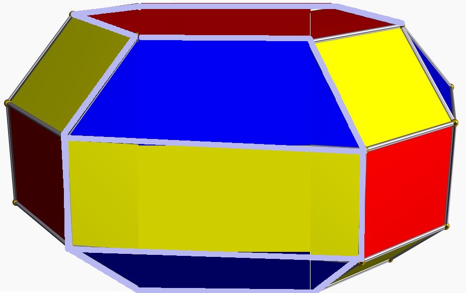
A rhombicuboctahedron has a central belt of eight squares that girdle it. On both sides of the central belt are belts of four squares that alternate with four equilateral triangles. At the very top are two squares; one at the top and one at the bottom.
Without going into any proof, I find that this shape meets the requirements of being a geodesic structure. In this the following quote by Professor Hugh Kenner inspires me to try new shapes:
It would help, moreover, if geodesic design could be disentangled from its historical reliance on spheres. More than once a geodesic approach has been shunned because the designer, for one good reason or for several, didn't want his structure to resemble a slice from a sphere. But anyone who masters the design procedure in this book will find that, once he has mastered geodesic spheres, geodesic eggs, whether tall or flat, are only one step more complicated, and free-form contours are no more difficult than eggs.
 Cover page of Geodesic Math by Hugh Kenner
Strength
Strength in shape of rhombicuboctahedron
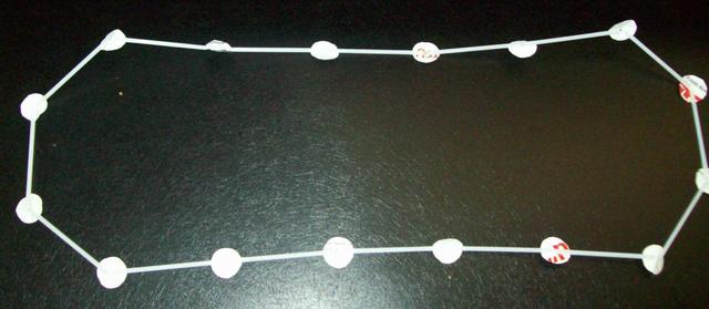
My recent workings with rhombicuboctahedron are pictured below. Rhombicuboctahedron made of CDs
 Rhombicuboctahedron made of transparent plastic
 Rhombicuboctahedron made of bamboo leaf
Only here has the classical rhombicuboctahedron shape been altered. The middle belt of squares is intact but the two upper and lower mixed belts of squares and triangles have had the squares replaced by rectangles, and the equilateral triangles replaced by isosceles triangles. The changed shape still retains its strength.
 Rhombicuboctahedron made of plain paper
 Rhombicuboctahedron decorated with flowers and bamboo leaves
 Rhombicuboctahedron made of newspaper broadsheets
Two newsprint broadsheets demonstrate the strength of the shape as such a huge shape made of flimsy material like a thin newsprint sheet still retains its shape despite any hidden wire skeleton. Most lamps of even the smaller size would require a wire skeleton in order to retain shape.
The Jump to Bamboo Tunnel
How can this shape be used to make a bamboo tunnel? I noticed that the shape could be truncated at any of the two horizontal two axis that are shown below.
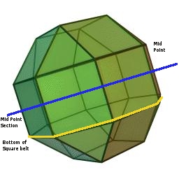
To my mind it made better sense to use the bottom of the square belt truncation( yellow in color) as the squares would provide the vertical walls that we are wanting in the bamboo tunnel.The Mid Point truncation (blue in color) gives only half the vertical height needed.
Stretching the rhombicuboctahedron
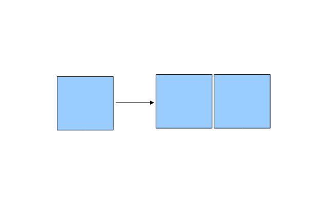
I decided that I would replace one square each on opposite sides with rectangles that would have twice the width of the square and leave the rest of the structure as it is.
or
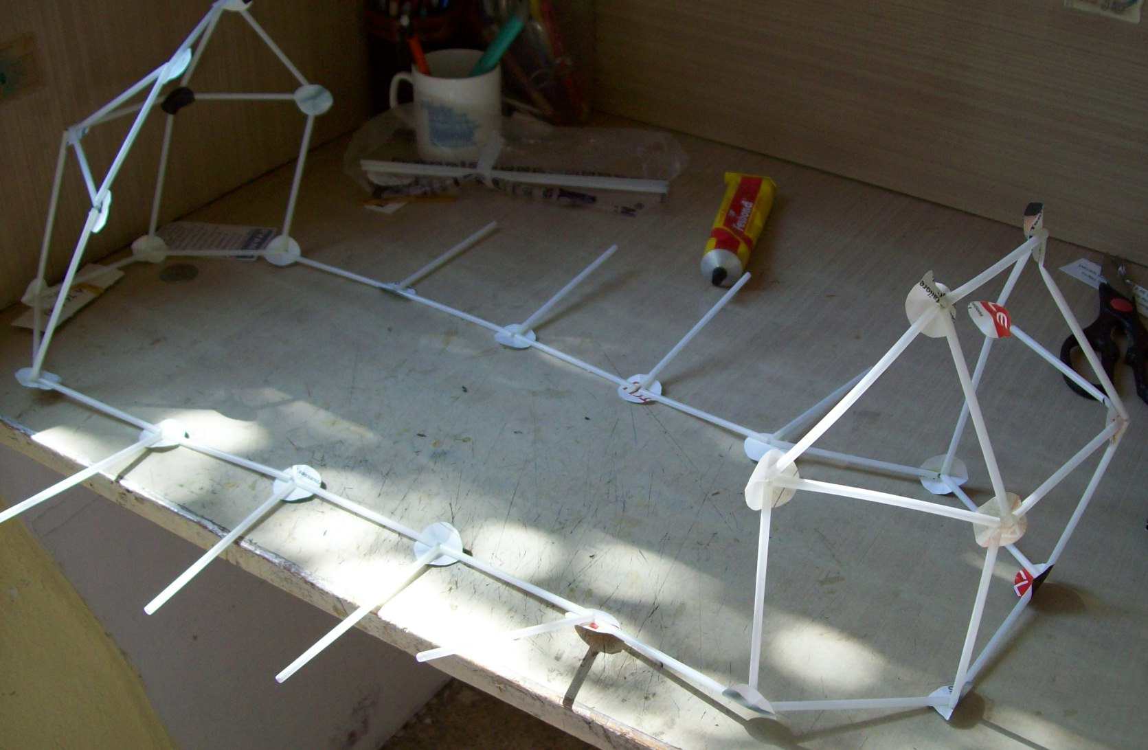
Straw Model
Stretched Model
First, the shape was assumed to be truncated at the bottom yellow line.Secondly, each central squares on opposite sides were replaced by two squares each stretching them into rectangles.This shape was modeled in plastic straws.This is the resulting model without the roof.
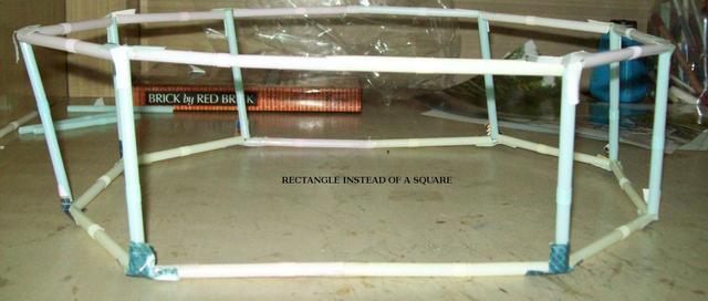 Two Rectangles instead of squares
I finished by adding the roof to the structure.
 With Roof Added.
Note that after working with plastic straw, I shifted to even more weaker plastic straws and hubs to bring in the reality that I was working with very weak materials.
End Cap View
The End Cap in this structure is the structure surrounding the long rectangle. The End Cap has three squares in the lower belt that are angled to each other. The top row has two equilateral triangles with a square between them. Its purpose is to prevent the long rectangle from leaning in the direction of its length.
 End Cap View
Model Size
In the three pictures shown above, imagine that each bamboo pole (Strut or chord technically) is about 6 foot long. Than the model will translates into a structure that is about 21 feet long and about 15 feet wide.
Design Structure
If the structure is to be about 40 feet long five bamboo poles have to be introduced where a second one was introduced. Conceptually it will look like this.
Weaknesses of rectangular structures
If a bamboo structure of this magnitude was to be successfully built, it had to overcome the weakness of traditional barn or shed designs, in particular, and rectangular buildings in general.
In such structures, the distribution of external loads is such that a load applied at a single point, either on a longitudinal face or on a traverse face, is transmitted unchanged to the opposite face by the longitudinal or transverse members that define the rectangle. If the force succeeds to make the face no longer true from vertical, then the force becomes self perpetuating and self aggravating one. As the face leans downward, it exerts more force (the increased force coming from gravity) on the face to lean down further until the whole structure falls.
Overcoming the weakness
The bamboo tunnel is designed as a geodesic structure and it is designed in such a manner that it has no longitudinal or transverse members at all! The photographs of the model that follow will show the presence of some ground hugging longitudinal members and two transverse members. They were left in as I was not confident of the strength of the designed structure and I need to locate some points in space. They are dispensable. The structure translates force applied at a single point into multiple forces in different directions such that the entire structure opposes the force applied. About half the force applied is opposed by itself.
Mathematics of design
The mathematics of design is shown in the appendix 1 to this document. It is really quite simple. The floor plan of the bamboo tunnel is shown below.
Bamboo Poles Sizes
The floor plan utilizes four different poles of sizes tabulated below.
| Description | Vertex to Vertex Length (In feet) | Numbers Needed | Total Running Feet | Cost (In Rupees) assuming ₹ 3/ running feet. |
| Seven foot vertical poles | 7 | 16 | 112 | 336 |
| Six foot poles | 6 | 22 | 132 | 396 |
| Mid Point Diagonals for 7 by 6 rectangles | 4.7 | 40 | 188 | 564 |
| Mid point Diagonals for 6 by 6 squares | 4.36 | 60 | 258 | 774 |
| Total | -- | 128 | 690 | 2070 |
The structure additionally requires about 40 hubs costing approximately ₹ 400 and about 16 feet of angle iron of 1.5 inch width. It also needs about 500 nuts, bolts and washers costing about ₹ 600.
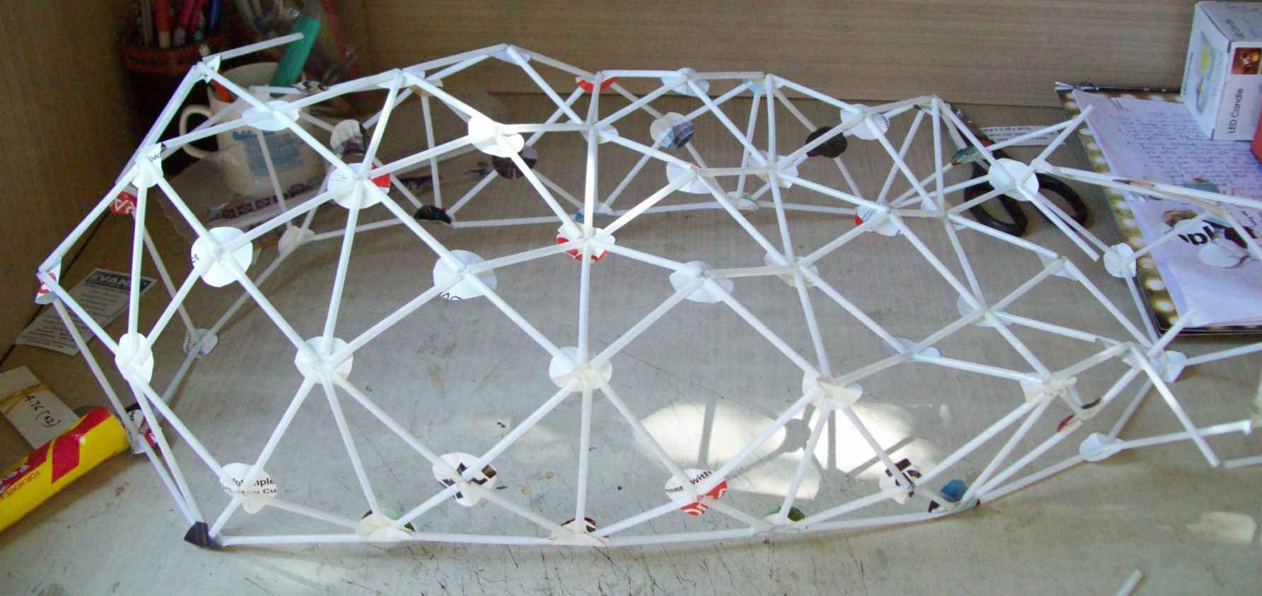
Assembly
Assembling the Tunnel
There are many ways to sequence the assembly of such a tunnel. As a general principle, I like to assemble it in a manner that I work at ground level for as long as possible and then portions already worked upon get pushed upwards. So work begins with assembling the highest points first and then working downwards till the base is reached at last.
Sub Assembly Roof of squares 6 by 6
First four poles were attached to a hub. Fifteen such sub assemblies were made. These assemblies were joined together to yield a three row by five column grid shown below.
 3 by 5 Grid assembly of 15 hubs
The grid sub assembly is 3d in nature with certain hubs being one foot above the plane of their ends.
 3d view
Ten 7 by 6 Grids
7 By 6 grids
As the hubs of 7 by 6 rectangles are to be attached to two opposite sides of the above grid, they were assembled separately from each other.
 7 by 6 Grids
Assembling the three grids
The 7 by 6 grids were then joined to 3 by 5 grid to give one huge roof grid.
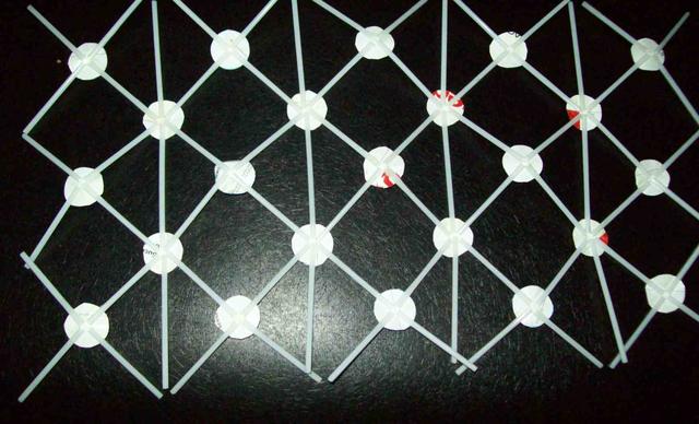
 All Grids assembled
The assembly is huge in size. It scales to a structure that is approximately 30 feet by 35 feet .But even now, the middle portions of the assembly are showing clear clean lines while the ends are sprawled all over.
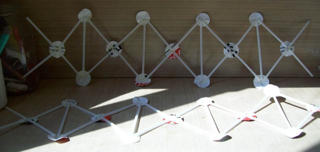
Base
Making a base
I then proceeded to assemble a base. It has four hubs at each of the end caps and four hubs on each long side of the rectangle. The base is not an essential feature of the structure and will be eliminated when making an actual tunnel.
 Base
Base
The hubs will be replaced by one foot deep angled iron stakes in the ground and the poles on ground will disappear.
End Caps
Another feature of this design of the bamboo tunnel is that it has an end cap at each of its end. End caps provide strength to the structure by resisting deformation of the structure in the longitudinal direction. Here the end caps are designed as an integral part of the geodesic structure.
 End Caps and Base
It can be seen that the two end caps do not look very strong and appear to have been twisted out of their shape even when there is no load on them.
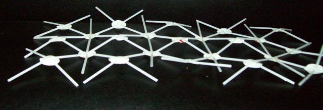
Joining the roof
First the roof is joined at one end cap. When that is done, the structure looks like something that a cat has dragged out of the dustbin!
 Roof joined at one end
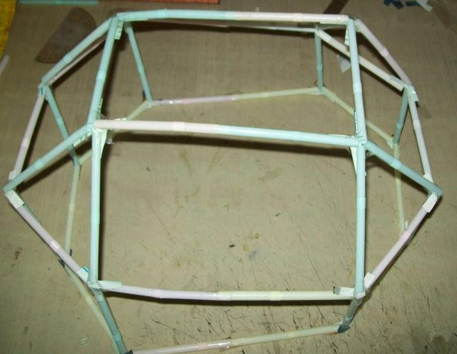
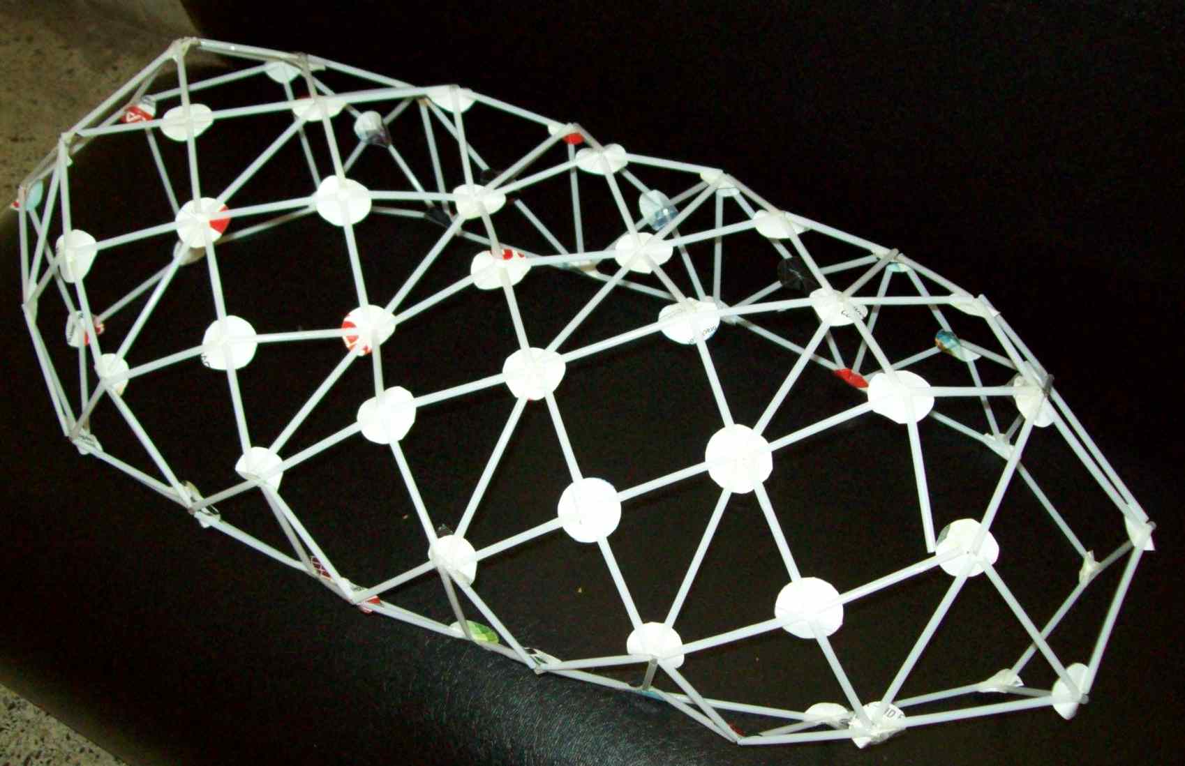
Final Assembly
When all the connections are made, the tunnel shows its true form and strength: This is typical behavior of a geodesic structure that its true strength is realized only when the hidden tension network can go around the whole structure. The grids and the End Caps rest in a dynamic tension pulling everything in a proper shape.
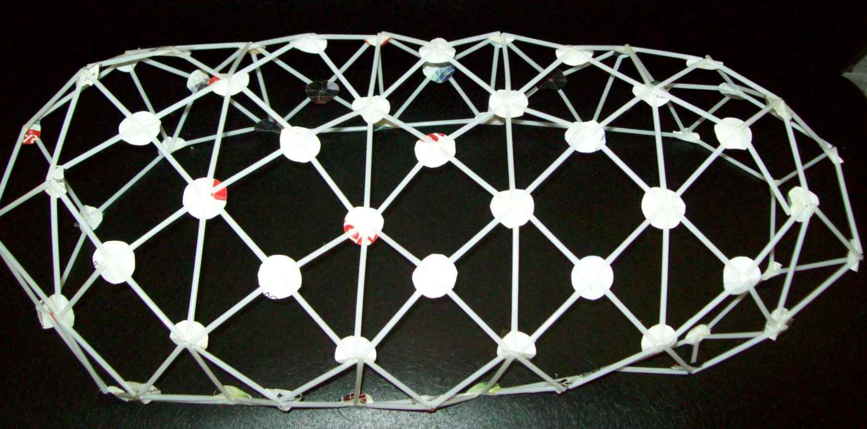 Top View
 Top View 2
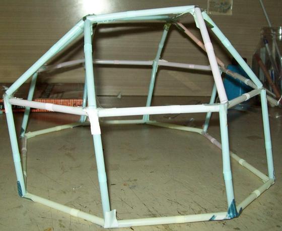
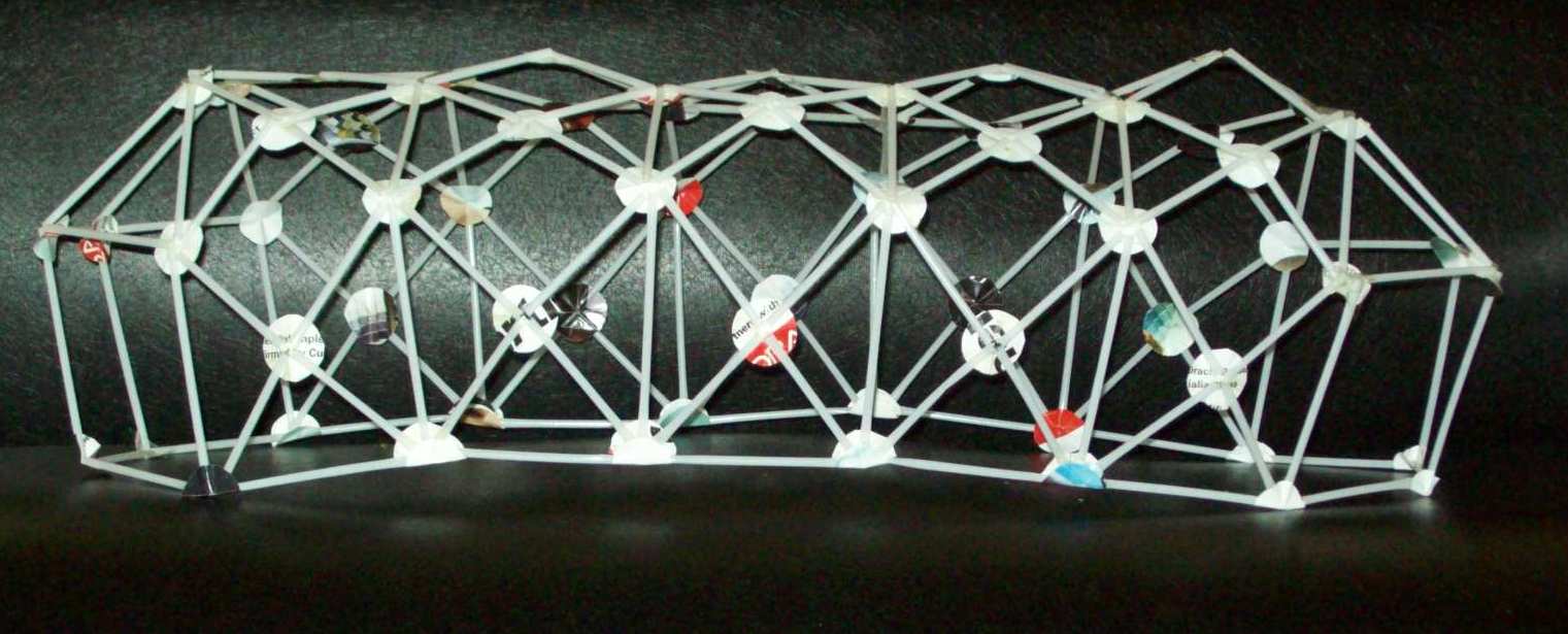 Side View
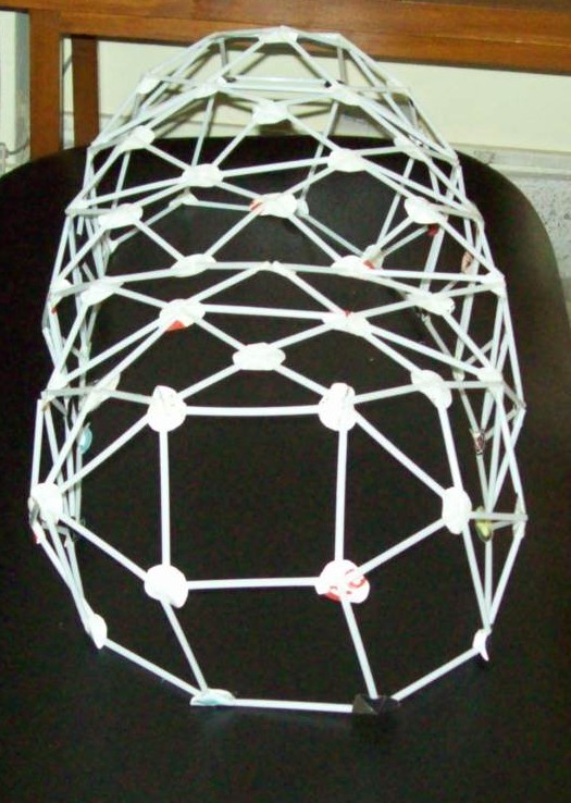 End View
Advantages of New Design
Quantitative advantages
If the two designs are to be directly compared, we need 3 modules of the first bamboo tunnel and only one of the second to cover comparable areas.
Area Covered:The three modules of the first design cover as area of 3 X 12 X 19 = 684 sq ft.The one module of the second design covers an area of 1 X 40 X 16 = 684 sq ft.
Bamboo lengths used: One module of first bamboo tunnel uses 223 rft of bamboo.Three modules use 3 X 223 = 669 rft of bamboo. The one module of second tunnel uses 690 rft of bamboo.So, on the face of it the two designs are very similar in terms of bamboo use. However if we were to incorporate the insights gained during the second design and were to redesign the first tunnel, we could save about 15 % of bamboo in the first design.
Usable area covered: In the first tunnel, from a width of 19 feet, only 12 feet are usable area. The rest cannot be directly used for horticulture.If we are going accept growing a single layer of plants instead of two layers of plants that the design calls for, then another 3 feet can be covered with a single layer of plants.Thus the effective area covered in the first tunnel is ( 12 + 3*0.5 = 13.5) * 36 = 486 sq ft. This is lower by 40% compared to the second design.
Qualitative Advantages
The end caps in the second design give additional strength to the structure. However the seven feet bamboo poles do constitute a point of weakness in the design.(For that matter vertical poles of any length are potential points of failure.) Out of 16 such poles, six can be designed away but the balance need to be left in the structure.However if slightly thicker bamboo are used for these poles, at a trivial cost, the defect can be worked away.
Traditional Structures of Polyhouses
The Design Requirements
There were two critical design requirements. Firstly there is need for a clear space twelve feet wide and seven feet high that runs throughout under the polyhouse. The polyhouse tunnel should be 38 feet long. Secondly it should be made of bamboo and should last about 10 years time.
The Proposed Design
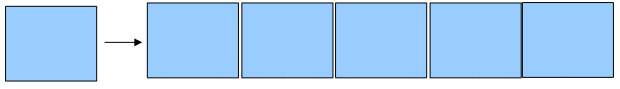
As I decided to make the tunnel in modules (hoops) that can be repeated endlessly and do not call for any end of the tunnel support, I have ignored the requirement of length of 38 feet. The repeating module has a length of 12 feet and three of them yield 36 feet length. Some minor fiddling in a spread sheet can yield either 3 modules whose length is exactly 38 feet or yield 4 modules whose total length is 38 feet. There is no real need to make any adjustment as the tunnel of length of 38 feet can easily be made by leaving gaps of one feet each between the two end tunnels and the middle tunnel as shown below. We can probably extend the length of a module up to 13 feet without any change in material used for construction.
The Traditional Design
Almost all tunnels and other long buildings are built as prisms. This includes most sheds as they are also built as prisms. A prism has two ends that are identical and these ends are connected by straight elements. Such a construction is very poor in its strength as any push at one end is transmitted unchanged to the other end of the building and it collapses, or sways in the wind. Once a prism tilts from the vertical, gravity comes into play and its weight tilts it more in that direction. Traditionally such prisms have bracings built at the corners to prevent swaying. Some pictures of traditional prisms are shown below.Mathematics of Design
- Non- Modular Design: This design is non-modular as the structure has End Caps on both its ends. The End Caps differ from the main structure.
- Middle Section Modular: The middle section is however modular in nature and within limits, its length cam be increased or shortened by adding/ reducing modules. It follows a hub and strut approach. By design most struts (bamboo poles) are identical in size and most hubs are also identical. If an important parameter is sacrificed, all hubs and struts in the middle section become identical.
- In terms of material used, it uses about 10% extra material compared to the first modular design but yields about 40% extra usable space. All space inside the structure is over 7 feet clear in height.
- The Structure: The consists of two symmetrical End Caps and five middle sections each of which are six foot long. Its overall length approaches 40 feet with a width of 16 feet. Both the End Caps and the middle section are designed using geodesic design considerations. In fact the End Caps are copied intact from a geodesic structure, the rhombicuboctahedron.
- Middle Section Design: The modular middle sections embody geodesic design of not allowing any direct longitudinal or traverse forces to be transmitted unchanged to the opposite faces by not having any such member or strut to transmit the force. By design faces are not planar but are 3D. This allows the entire structure to resist any distorting force. The middle section consists of square grids for most parts but changes to some near square grids to take care of the requirement of 7 feet clear space when it uses 7 by 6 grids instead of 6 by 6 grids.
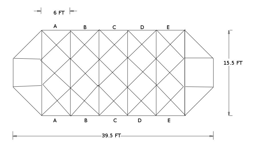
- Floor Plan: The middle sections A,B,C,D,and E are each 6 feet wide. The End Cap has its middle pole as 6 feet long, while the two side poles, also 6 feet long, are at 135 degrees to it. Without taking into account the tiny increases in size that result from use of hubs, the structure is 39.5 feet long and 15.6 feet wide. Poles that are in the air are shown by disjoint lines. Hubs are shown as small circles in the diagram.
Floor Plan
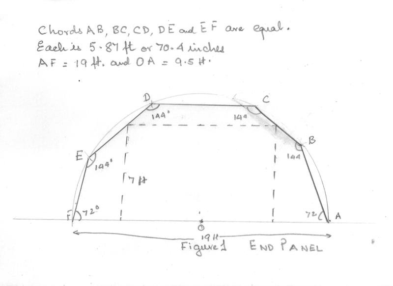
- End Cap View: The vertical bamboos are 7 feet high while all other struts are 6 feet. The angle between the three struts at the bottom and middle is 135 degrees. The two equilateral triangles have 60 degree angles and sides of 6 feet.
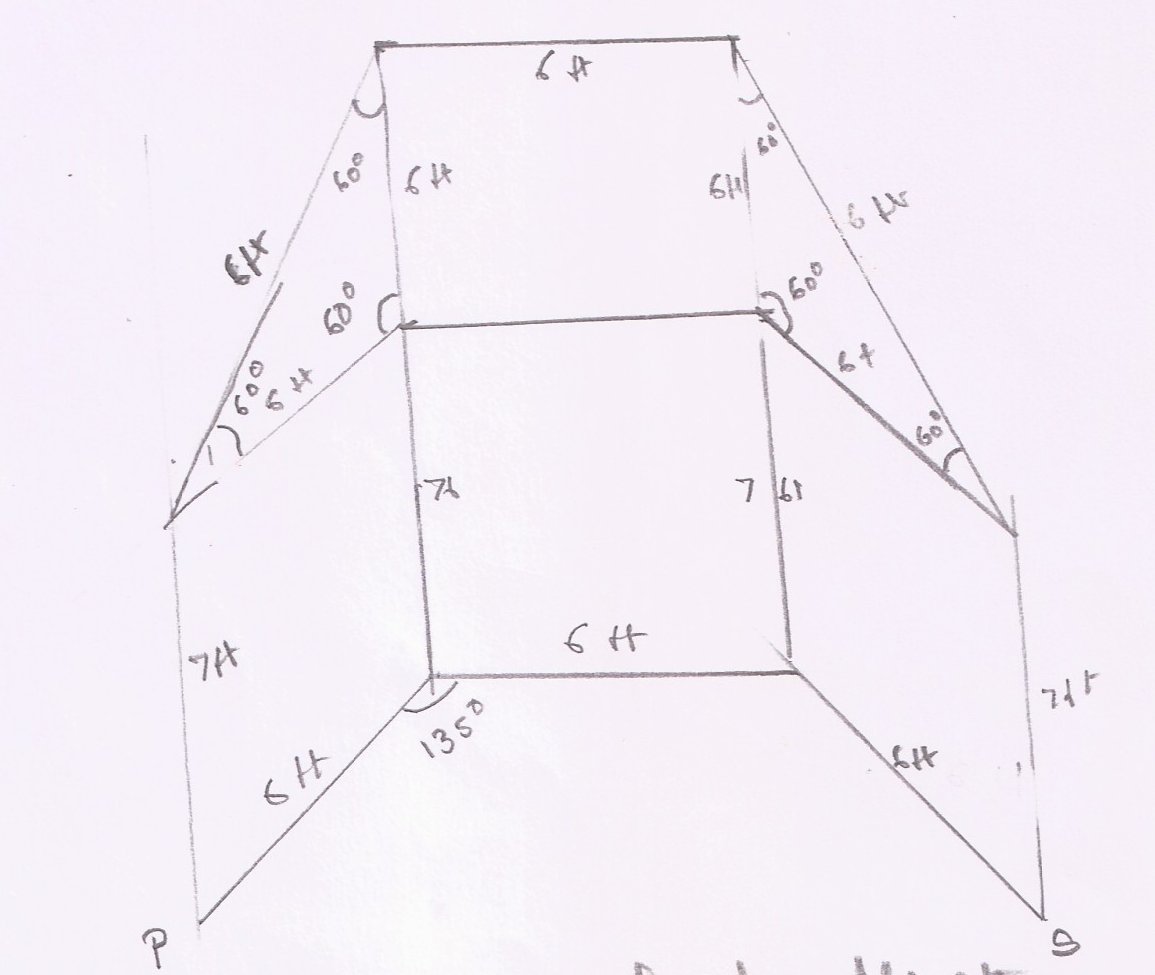
- Diagonals 7 by 6 grids: In all the grids, arbitrarily, the point where the mid points of the diagonals meet, and where a hub will sit, are designed to be 1 foot over the plane where the other ends of struts will sit. The rectangle ABCD represents one such 7ft by 6 ft grid.
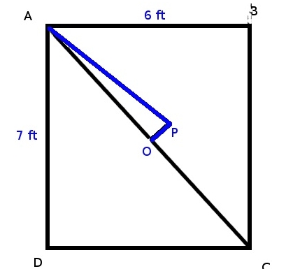
Diagonal AC = √ 7*7 + 6*6 = √49 + 36 = √85 = 9.2 ft
AO = half AC = 4.6
Diagonal AP where OP is 1 foot high = √4.6 * 4.6 + 1* 1 = √21.16 + 1 = √22.16 = 4.7 ft
- Diagonals 6 by 6 grids
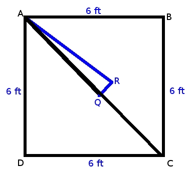 Diagonals 6 by 6 grids.
Diagonal AC = √ 6*6 + 6*6 = √36 + 36 = √72 = 8.48 ft
AQ = half AC = 4.24
Diagonal AR where QR is 1 foot high = √4.24 * 4.24 + 1* 1 = √17.91 + 1 = √18.91 = 4.36 ft
- Hubs: All hubs are essentially identical. I prefer them to be six inches in diameter. They all have eight sets of holes (2 holes with a spacing on one inch between them) where the poles will be screwed. These holes are 45 degrees apart. Eight hubs each in the End Cap will be bent till the two halves are at 135 degrees to each other.
- Nuts and Bolts: I prefer holes in bamboos and hubs to be 5 mm in diameter and prefer using 4 mm , 2 inch long nuts and corresponding hexagonal bolts and ms washers.
External Links to Other Designs
- A wooden poly house that uses eucalyptus poles that are twice to four times thicker. http://www.indg.in/agriculture/ruraltechnologies/wooden-green-house
- Conventional green houses made of iron. http://agritech.tnau.ac.in/horticulture/horti_Greenhouse%20cultivation.html
- National Bamboo Mission supports this type of Bamboo Tunnel It sells for ₹ 300 per square meter but that includes UV coated polyester and erection also. http://indiabambooallinall.org/Default.aspx?tabid=39&catid=140&prodid=122145
- Patent on which NBM polyhouse is based. http://india.bigpatents.org/apps/1JZj5bgG
- Thousand Petals Polyhouses Pvt. Ltd makes polyhouses to boost agricultural productivity for Indian farmers. http://www.thousandpetals.in/
Tunnels of various types have been proposed for Agricultural purposes. These links focus more on agricultural benefits/costs rather than methods of construction.
- High Tunnels http://www.hightunnels.org/ForGrowers/SitePlanning&Construction/Articles/CareyHow-toBuild.htm http://www.hightunnels.org/PDF/How_to_Build_a_High_Tunnel_Ferguson_Univeristy_of_Kentucky.pdf http://www.hightunnels.org/PDF/Hoop_House_Construction_for_New_Mexico.pdf
- Problems of tunnels http://www.facebook.com/pages/Tunnel-farming-in-Pakistan/197059440355571
- Low Tunnels http://www.facebook.com/photo.php?fbid=198470273547821&set=a.198470190214496.51000.197059440355571&type=1&theater http://www.facebook.com/media/set/?set=a.198470190214496.51000.197059440355571&type=1